CHALLENGE INFORMATION
 | Platform: TryHackMe Module: Malware Analysis Room: x86 Architecture Overview |
DESCRIPTION:
A crash course in x86 architecture to enable us in malware reverse engineering.
Learning Objectives
- Overview of CPU architecture and its components
- Different types of CPU registers and their usage
- Memory layout as viewed by a program
- Stack layout and stack registers
Introduction
Question 1: Go through the Learning Objectives
No answer needed
CPU Architecture Overview
This section explains the basic components of a CPU – Control Unit, Arithmetic Logic Unit, and Registers – and how they interact with external devices – Memory and I/O devices.
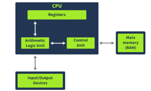
The following is a brief overview:
- Control Unit: Fetches instructions from memory and executes them one at a time.
- Arithmetic Logic Unit: Performs calculations and operations based on those instructions.
- Registers: Small, high-speed storage areas that hold important data for quick access by the CPU.
- Memory (RAM): Stores all program code and data.
- I/O devices: Include keyboards, displays, printers, and other peripherals that interact with the computer.
Overall, the room provides a simple explanation of how a CPU executes instructions and interacts with external components to run programs.
Question 1: In which part of the Von Neumann architecture are the code and data required for a program to run stored?
Memory
Question 2: What part of the CPU stores small amounts of data?
Registers
Question 3: In which unit are arithmetic operations performed?
Arithmetic Logic Unit
Registers Overview
The room continues with an explanation of the concept of registers as the CPU’s storage medium, which provides quick access to data compared to other storage media.
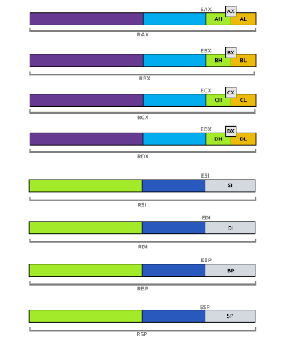
The registers are divided into several types:
- Instruction Pointer (IP/RIP): A register that stores the address of the next instruction to be executed by the CPU.
- General-Purpose Registers: These 32-bit or 64-bit registers store data during general execution of instructions by the CPU. They include:
- EAX/RAX, EBX/RBX, ECX/RCX, EDX/RDX: Accumulator, Base, Counter, and Data Registers
- ESP/RSP, EBP/RBP, ESI/RSI, EDI/RDI: Stack Pointer, Base Pointer, Source Index, and Destination Index Registers
- R8-R15: 64-bit general-purpose registers not present in 32-bit systems
These registers are used to store data temporarily while it is being processed by the CPU. The room also explains how each register type can be addressed at different levels of precision (e.g., byte, word, double-word).
Question 1: Which register holds the address to the next instruction that is to be executed?
Instruction Pointer
Question 2: Which register in a 32-bit system is also called the Counter Register?
ECX
Question 3: Which registers from the ones discussed above are not present in a 32-bit system?
R8-R15
Status and Segment Registers
Status Flag Registers - Indicating Execution Status
This section explains the concept of Status Flag Registers, which provide information about the status of execution in a CPU. These registers are:
- EFLAGS (32-bit) and RFLAGS (64-bit): Single 32-bit or 64-bit registers that contain individual single-bit flags.
Some key flags include:
- Zero Flag (ZF): Indicates when the result of an instruction is zero.
- Carry Flag (CF): Indicates when a number is too large or too small for the destination register.
- Sign Flag (SF): Indicates if a result is negative or has the most significant bit set to 1.
- Trap Flag (TF): Indicates if the processor is in debugging mode.
Segment Registers - Organizing Memory
The room also explains Segment Registers, which are used to organize memory into different segments for easier addressing. There are six segment registers:
- Code Segment (CS): Points to the code section in memory.
- Data Segment (DS): Points to the program’s data section in memory.
- Stack Segment (SS): Points to the program’s stack in memory.
- Extra Segments (ES, FS, GS): Divide the program’s memory into four distinct data sections.
Question 1: Which flag is used by the program to identify if it is being run in a debugger?
Trap Flag
Question 2: Which flag will be set when the most significant bit in an operation is set to 1?
Sign Flag
Question 3: Which Segment register contains the pointer to the code section in memory?
Code Segment
Memory Overview
When a program runs on Windows, it sees an abstracted view of memory, with its own memory space isolated from the rest of the system. Program memory layout:
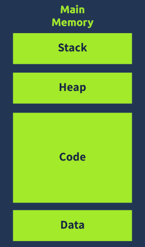
The program has access to four main sections of memory:
- Code: Contains the program’s instructions and code, which can be executed by the CPU.
- Data: Holds initialized data that remains constant during execution, including global variables.
- Heap (Dynamic Memory): Allocates and deallocates memory for variables created and destroyed at runtime.
- Stack: Stores local variables, function arguments, and return addresses, which can be targeted by malware to hijack control flow.
The room also provides a brief overview of each section, highlighting their characteristics and importance in malware analysis.
The stack is emphasized as a critical area from a malware perspective, particularly due to its role in controlling the program’s execution flow.
Question 1: When a program is loaded into Memory, does it have a full view of the system memory? Y or N?
N
Question 2: Which section of the Memory contains the code?
Code
Question 3: Which Memory section contains information related to the program’s control flow?
Stack
Stack Layout
The stack is a critical part of a program’s memory that contains local variables, function arguments, and control flow information. It is essential for malware analysis and reverse engineering.
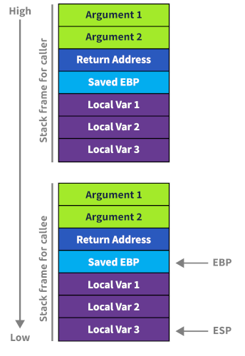
The stack follows a last in, first out (LIFO) principle, where the last element added is the first to be removed.
Stack Pointers
The CPU uses two registers to manage the stack:
- Stack Pointer (ESP/RSP): Points to the top of the stack, adjusting as elements are pushed or popped.
- Base Pointer (EBP/RBP): Remains constant for a program, tracking local variables and arguments.
Function Prologue and Epilogue
When a function is called:
- The function prologue pushes arguments, the return address, and the old base pointer onto the stack.
- The base pointer address changes to point to the top of the stack (the current stack pointer).
When a function exits:
- The function epilogue pops the old base pointer and return address, then rearranges the stack pointers.
Malware Technique - Stack Buffer Overflow
A common malware technique is to overflow a local variable on the stack, overwriting the Return Address with an attacker’s chosen address. This can hijack control flow and execute malicious code.
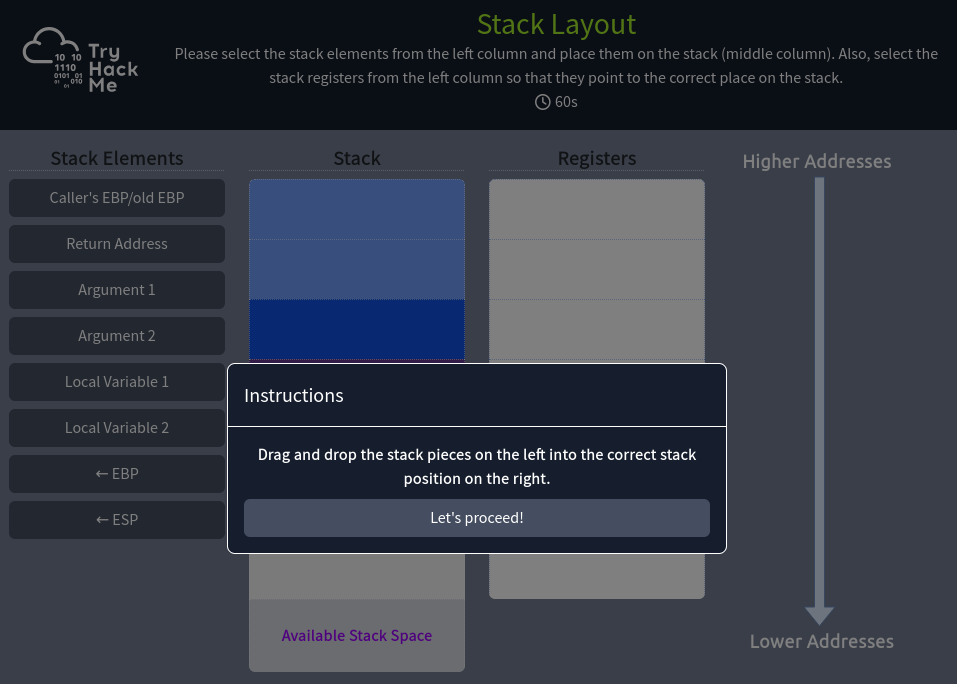
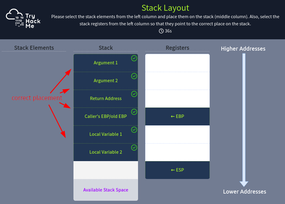
The room concludes by asking us to arrange the stack correctly on a static site to find a flag.
The correct arrangement appears as follows:
Copy the flag to answer the question below.
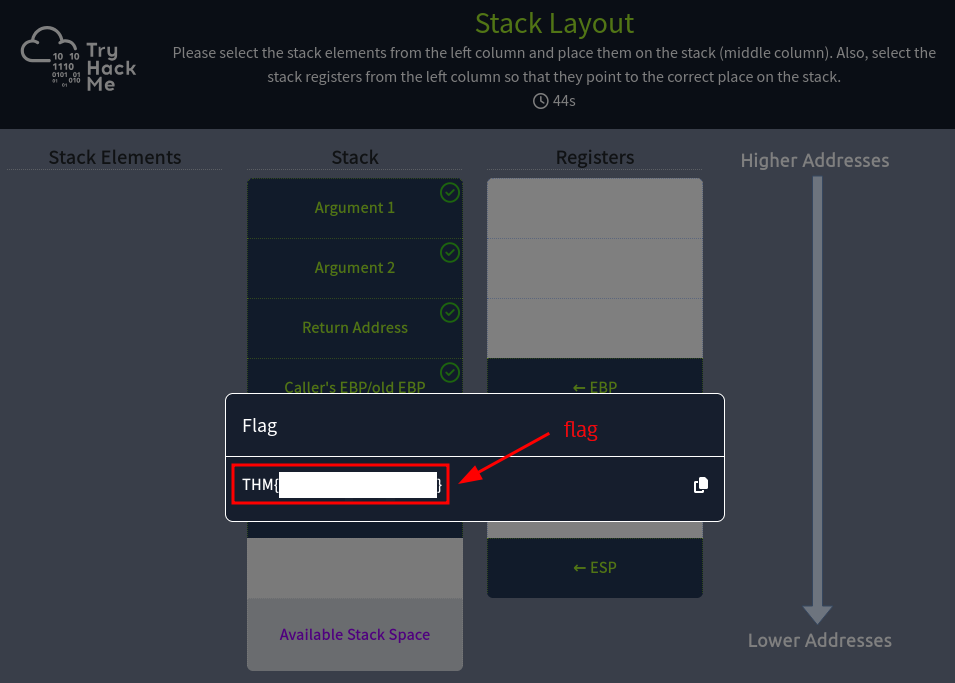
Question 1: Follow the instructions in the attached static site and find the flag. What is the flag?
<redacted-flag>
Conclusion
Question 1: Join the discussion on our social channels
No answer needed