Challenge Information
Platform: TryHackMe
Path: Pre Security
Module: Network Fundamentals
Room: Intro to LAN
Description: Learn about some of the technologies and designs that power private networks
Introducing LAN Topologies
This section features an interactive laboratory environment demonstrating three primary network topologies: ring, bus, and star. Each topology is presented with graphical demonstrations illustrating its structure, operation, and inherent vulnerabilities. The objective requires exploiting each topology’s weakness to disrupt the network; the flag is revealed only after all three networks have been successfully compromised.
Figure 1: Network topologies lab
Ring Topology
In a ring topology, devices are connected in a circular configuration where data travels in one direction until it reaches its destination. While this design eliminates collision domains, it introduces a critical single point of failure.
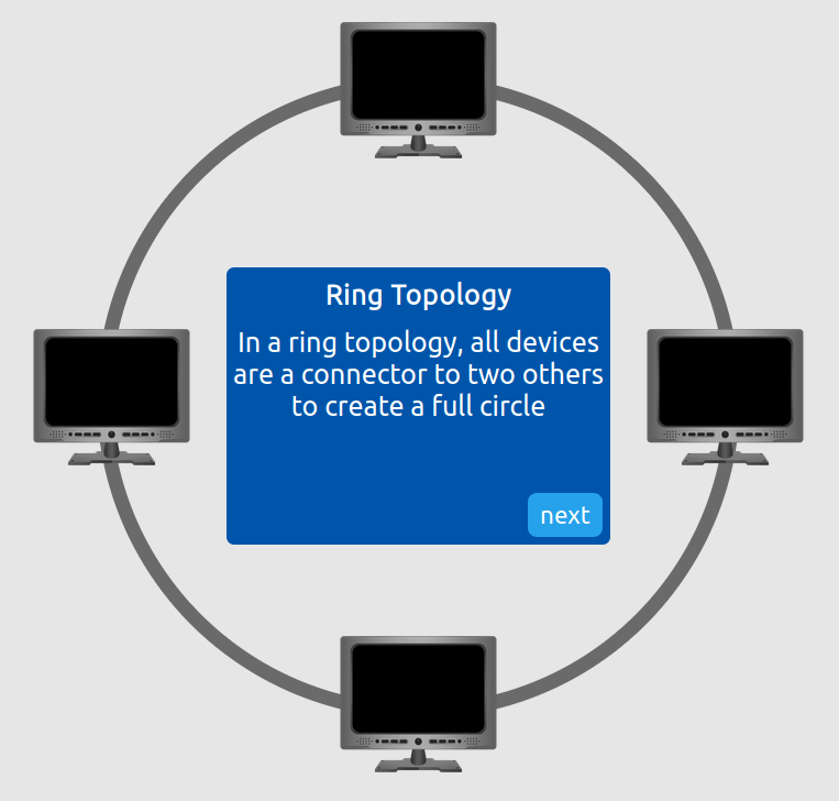
Figure 2: Ring topology definition
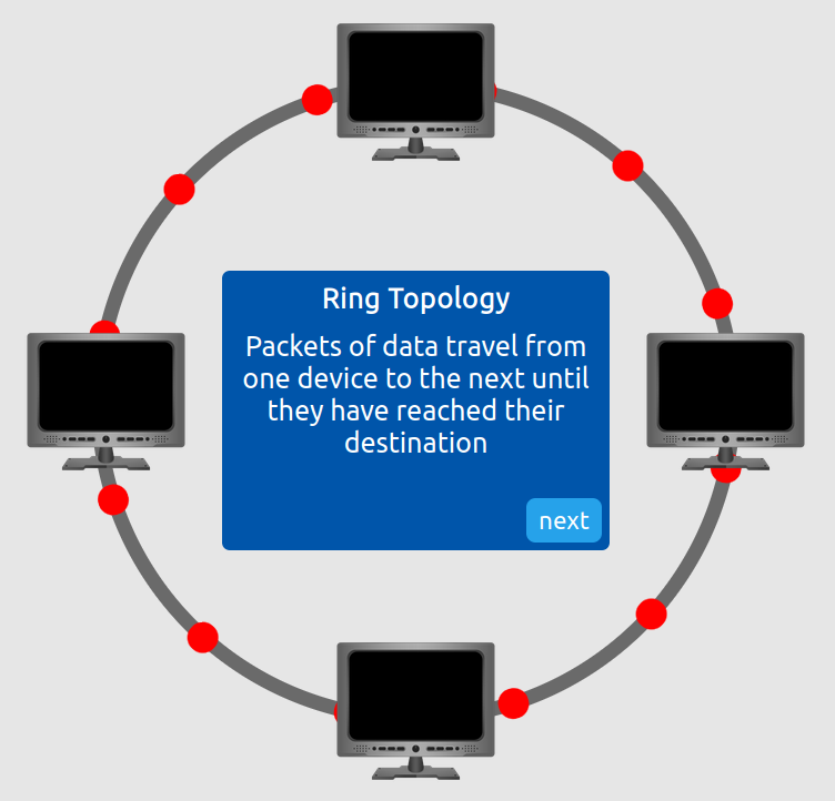
Figure 3: Ring topology demonstration
The vulnerability lies in the topology’s dependency on every node functioning correctly. If any device fails or the connection between devices is severed, the entire network ceases to function.
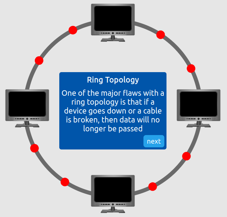
Figure 4: Ring topology vulnerability
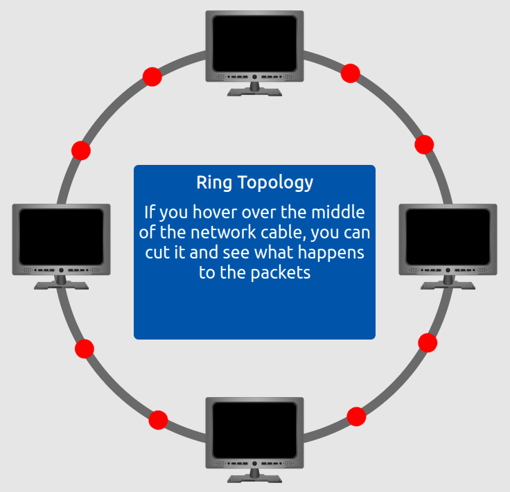
Figure 5: Ring topology exploitation
We exploited this vulnerability by severing the connection between two nodes, thereby breaking the ring and disrupting network communications.
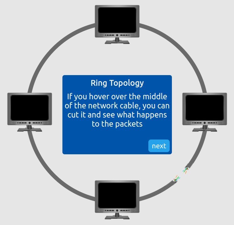
Figure 6: Broken ring topology, stage 1
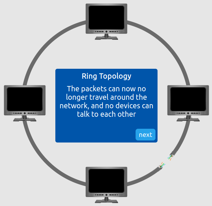
Figure 7: Broken ring topology, stage 2
Bus Topology
Bus topology employs a single backbone cable to which all devices connect. While cost-efficient and simple to implement, this design presents significant security and reliability concerns.
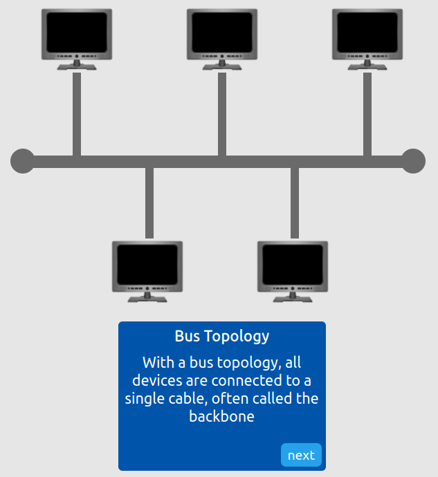
Figure 8: Bus topology definition
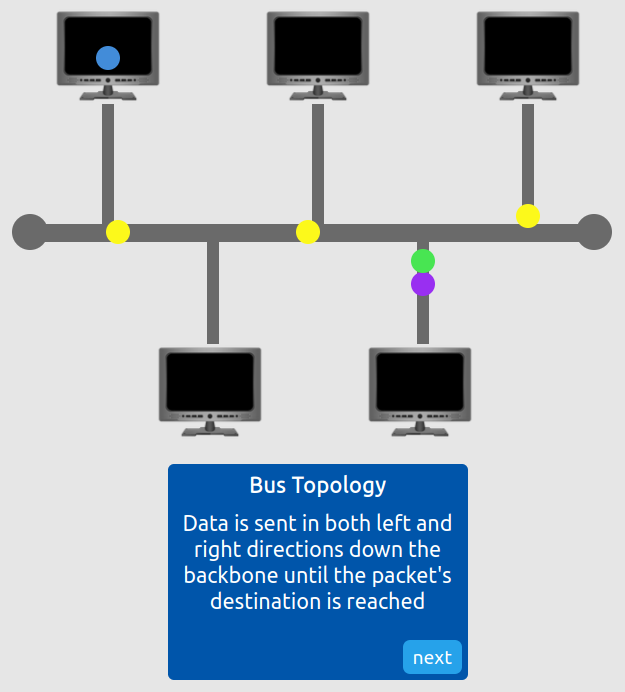
Figure 9: Bus topology demonstration
The primary vulnerability stems from the fact, when data is sent, it is sent down the backbone, in both left and right directions. All destinations will receive that data. Sending enough data can therefore overwhelm the backbone cable.
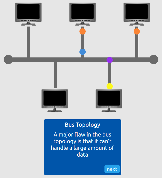
Figure 10: Bus topology vulnerability
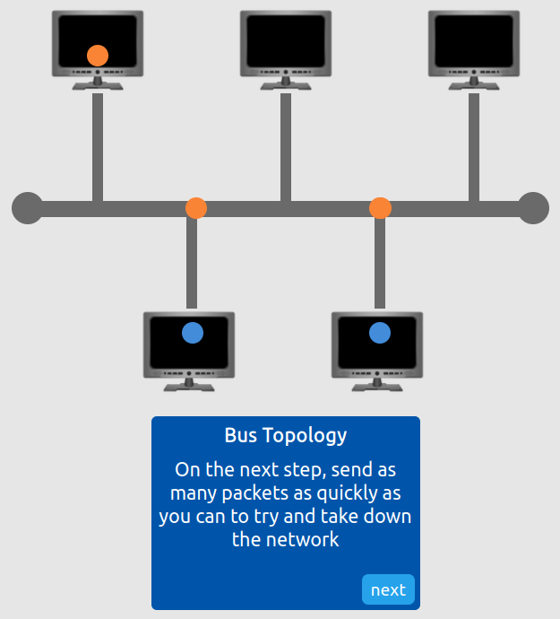
Figure 11: Bus topology exploitation, stage 1
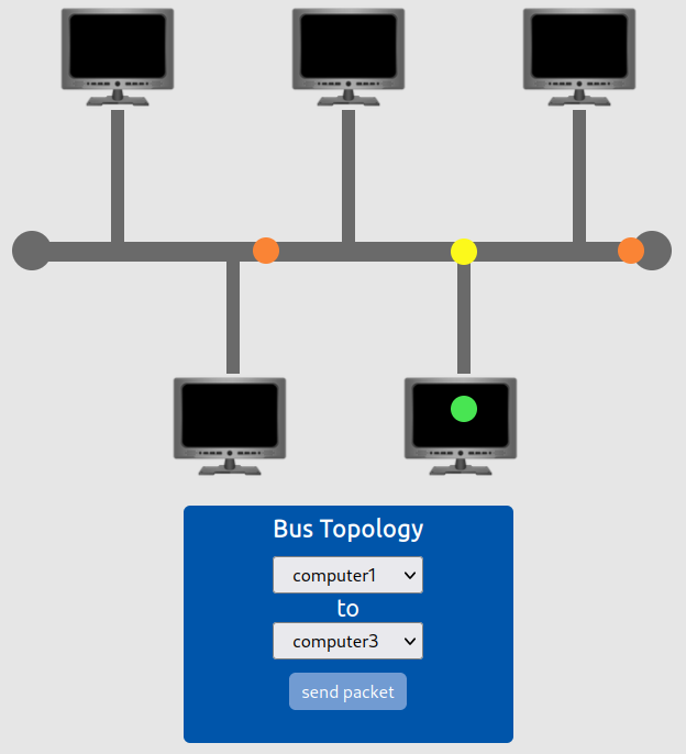
Figure 12: Bus topology exploitation, stage 2
By sending a lot of data down the backbone cable, we successfully disrupted all network communications.
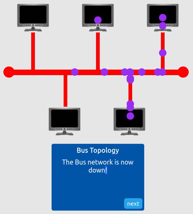
Figure 13: Broken bus topology
Star Topology
In a star topology, all devices connect to a central hub or switch. This configuration offers improved reliability and simplified troubleshooting compared to ring or bus topologies, though it introduces dependency on the central device.
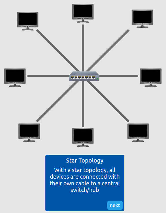
Figure 14: Star topology definition
The central device represents a single point of failure; if compromised, the entire network becomes inoperable.
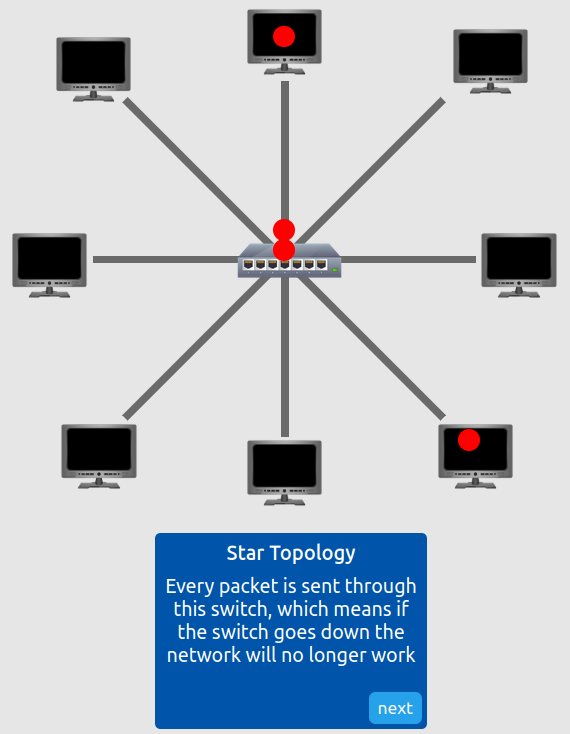
Figure 15: Star topology vulnerability
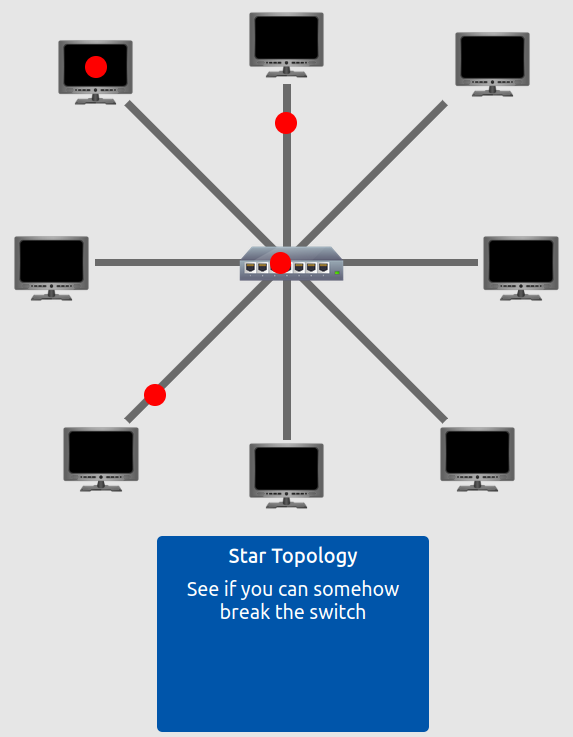
Figure 16: Star topology exploitation
We disabled the central switch, thereby terminating all network communications between connected devices.
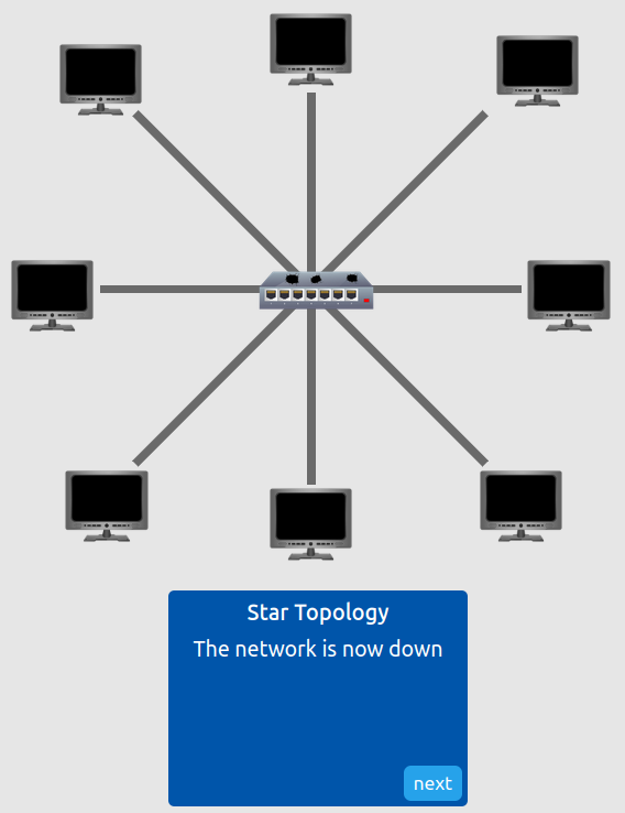
Figure 17: Broken star topology
With all three topologies compromised, the challenge flag was revealed.
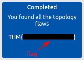
Figure 18: Redacted flag
Questions and Answers
Question 1: What does LAN stand for?
Local Area Network
Question 2: What is the verb given to the job that routers perform?
Routing
Question 3: What device is used to centrally connect multiple devices on the local network and transmit data to the correct location?
Switch
Question 4: What topology is cost-efficient to set up?
Bus topology
Question 5: What topology is expensive to set up and maintain?
Star topology
Question 6: Complete the interactive lab attached to this task. What is the flag given at the end?
<redacted-flag>
A Primer on Subnetting
This section introduces subnetting, the process of dividing a network into smaller, more manageable segments. Understanding subnetting is essential for network design, security segmentation, and efficient IP address allocation.
Question 1: What is the technical term for dividing a network up into smaller pieces?
Subnetting
Question 2: How many bits are in a subnet mask?
32
Question 3: What is the range of a section (octet) of a subnet mask?
0–255
Question 4: What address is used to identify the start of a network?
Network address
Question 5: What address is used to identify devices within a network?
Host address
Question 6: What is the name used to identify the device responsible for sending data to another network?
Default gateway
The ARP Protocol
The Address Resolution Protocol (ARP) enables devices to map logical IP addresses to physical MAC addresses. This protocol is fundamental to local network communication and plays a critical role in network reconnaissance and potential exploitation.
Question 1: What does ARP stand for?
Address Resolution Protocol
Question 2: What category of ARP packet asks a device whether or not it has a specific IP address?
Request
Question 3: What address is used as a physical identifier for a device on a network?
MAC address
Question 4: What address is used as a logical identifier for a device on a network?
IP address
The DHCP Protocol
The Dynamic Host Configuration Protocol (DHCP) automates IP address assignment, enabling devices to join networks without manual configuration. This section examines the four-step DHCP process: Discover, Offer, Request, and Acknowledge (DORA).
Question 1: What type of DHCP packet is used by a device to retrieve an IP address?
DHCP Discover
Question 2: What type of DHCP packet does a device send once it has been offered an IP address by the DHCP server?
DHCP Request
Question 3: Finally, what is the last DHCP packet that is sent to a device from a DHCP server?
DHCP ACK
Continue Your Learning: OSI Model
Completion of this room concludes the Network Fundamentals module’s introduction to local area networking. The next room in the learning path covers the OSI model, which provides a conceptual framework for understanding network communication across seven distinct layers.
Question 1: Join the OSI Model room room.
No answer needed